 English
 Deutsch
 Français
 Español
 Nederlands
 Polski
 Italiano
 Română
 Türkçe
 Português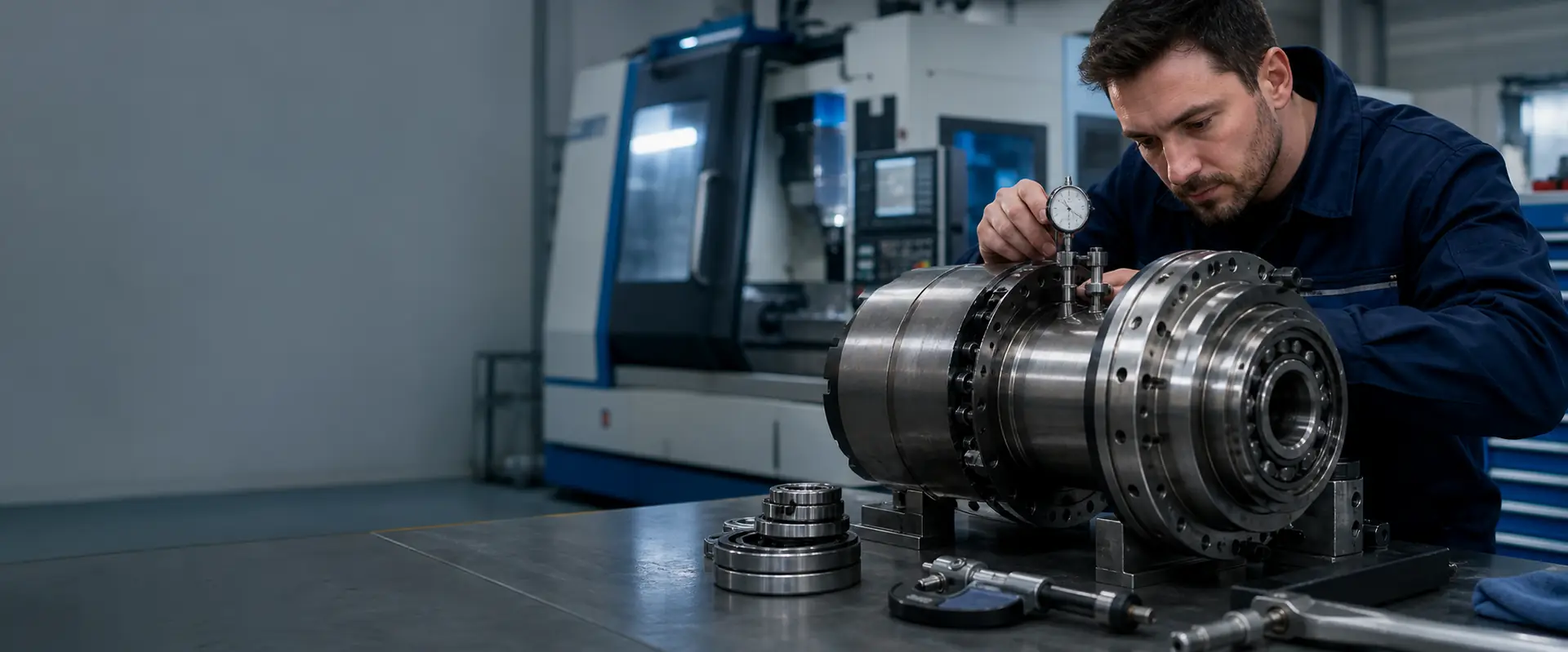
Final stage
Spindle dynamic balancing
Every rotating assembly carries some residual unbalance. At a few thousand revolutions it is harmless; at high speed it loads the bearings continuously and shows up in the surface finish. Balancing is the last stage of a rebuild, and occasionally a job on its own once a spindle has been disturbed.
Process
Order of work
-
1
Component check first
Balancing corrects neither a bent shaft nor a damaged taper nor worn bearings. Geometry and runout are measured first, and if something is out we report it before balancing.
-
2
Balance the rotating assembly
The shaft with rotor, spacers and fitted components is set up on the balancing machine and corrected in two planes until residual unbalance is within the target for that assembly.
-
3
Assemble and run in
The spindle is built up, lubrication set to the specified quantity, and run in stepwise through its speed range while bearing temperature and vibration are recorded at each step.
-
4
Final measurement and report
Vibration is measured in the assembled spindle at operating speed, runout is rechecked at the tool interface, and the values are issued as a test report with the spindle.
Scope
How the balancing work is done
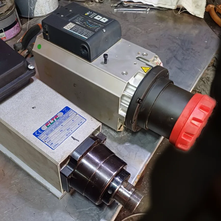
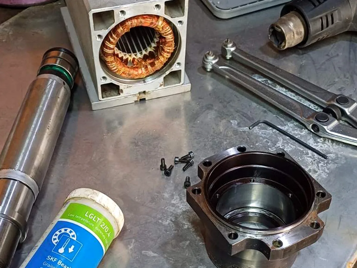
The rotating assembly is balanced in two planes on a balancing machine, then checked again in the assembled spindle at running speed. Correction is made where the design provides for it: balancing rings, grub screw pockets or material removal at defined points. Where a component has no correction provision, we say so rather than improvising one.
Two-plane correction
A spindle rotor is long relative to its diameter, so single-plane correction leaves a couple unbalance behind. Correction is made in two planes, which addresses the static and the moment component together.
Balance grade targets
Where the design and the correction provision allow, we work towards ISO 21940 grades in the G2.5 to G1 range, chosen for the operating speed. The grade actually reached is stated in the report.
Residual unbalance recorded
Residual unbalance is measured in gramme millimetres for each plane, together with the speed at which it was measured. Those figures go into the test report rather than being summarised as a pass.
Behaviour at operating speed
A rotor balanced only on a balancing machine can still run rough in its own housing. Final checking is done in the assembled spindle across its speed range, where preload and fits influence the result.
Checklist
What we ask before balancing
- Maximum operating speed and the normal working range
- Tool interface type and the holder used in service
- Whether the spindle has been dismantled previously
- Any vibration readings taken on the machine
Questions
Dynamic balancing spindle repair — frequently asked
That depends on the design, the correction provision and the condition of the parts. Where the assembly allows it we target the G2.5 to G1 range under ISO 21940, formerly ISO 1940. We do not promise a grade in advance; the value measured is stated in the report.
A balancing machine holds the rotor in its own soft bearings. In service the rotor sits in preloaded angular contact bearings inside a housing, where fits, spacers and preload all affect behaviour. Checking at operating speed shows what the machine will actually see.
Sometimes, often not. Vibration also comes from worn bearings, a bent shaft, a damaged taper, an unbalanced tool holder or the machine structure itself. We measure before assuming, and if the cause is not the rotating assembly we tell you rather than balancing it anyway.
The rotating assembly is balanced as part of a bearing change or a motor rebuild where that work has disturbed it, and it is covered in the quotation for the rebuild. Balancing as a standalone job is quoted separately after the incoming inspection.
When it is needed
When unbalance is worth investigating
Vibration that grows with speed
Unbalance force rises with the square of speed. A spindle that is quiet at low revolutions and rough at the top of its range is a candidate for checking.
Finish problems at high speed only
Chatter or a patterned finish that appears above a certain speed, with the same tool and holder that works well lower down, points at the rotating assembly.
After a crash or a component change
Anything that disturbs the rotor, a collision, a replaced pulley, a new drawbar assembly, alters the balance state of the spindle and is worth measuring.
Ask about a balancing job
Tell us the spindle type, its maximum speed and what the vibration is doing. We will say whether balancing alone is likely to help or whether the spindle needs inspecting first.
Scope
Spindle work we carry out for customers in Dynamic balancing
Every operation below is done in our own workshop in Germany. Follow a link for what it involves and what we need from you.
Machine brand
Machine brands
We are independent and not tied to any builder. These are the makes whose spindles come across the bench most often.