 English
 Deutsch
 Français
 Español
 Nederlands
 Polski
 Italiano
 Română
 Türkçe
 Português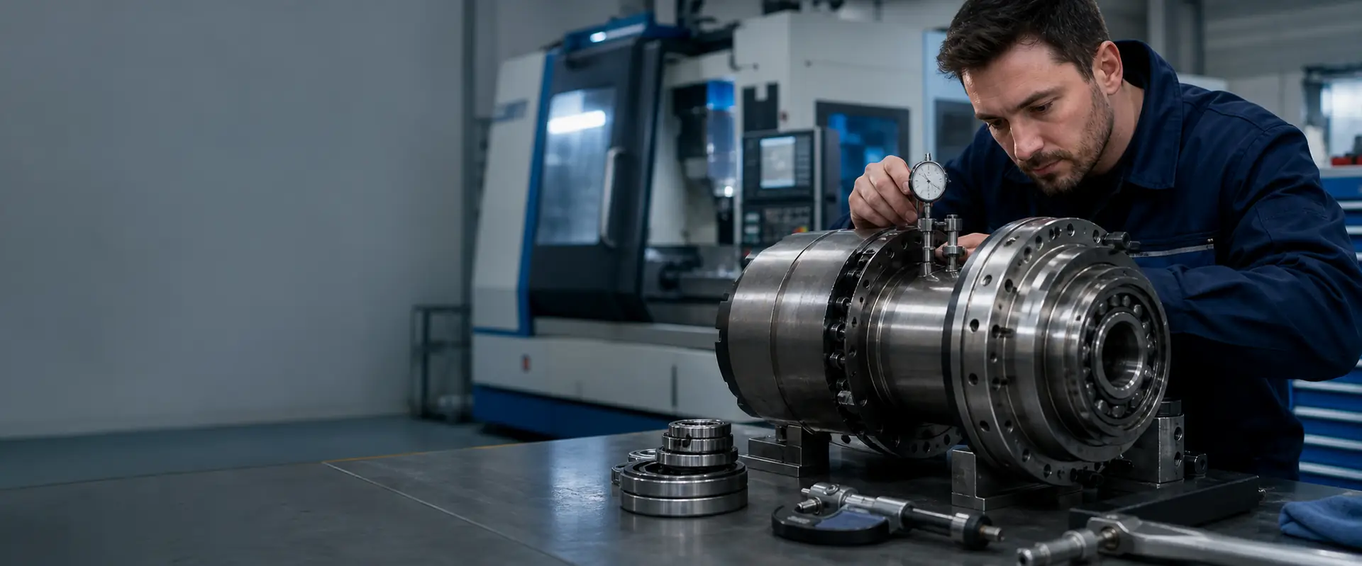
Feedback
Spindle encoder and sensor repair
The spindle tells the control where it is and how fast it is turning. When that signal degrades, the machine reacts to something that never happened: orientation faults at tool change, speed errors, a drive that trips with nothing mechanically wrong. This work covers the encoder, its sensors, its cabling and its mounting.
When it is needed
Faults that usually come back to feedback
Tool change stops in the wrong place
Orientation drifts, the drawbar fights the taper, or the changer alarms. A reference mark that has moved, or a disc with swarf on it, produces exactly this.
Speed and following errors
The control reports a speed the spindle is not running, or trips on a following error, while the mechanical side sounds perfectly normal at the same load.
Alarms that only arrive warm
Everything is fine from cold and the fault appears after twenty minutes. Marginal cable cores, corroded connectors and a disc running close to its air gap all behave this way.
Scope
What the encoder work includes
Feedback faults get blamed on the spindle and on the drive, and both are wrong about half the time. The work begins by establishing which end of the loop is actually at fault. We repair or replace the encoder, its sensors and its mounting; whatever belongs in the drive cabinet is measured as far as the readings allow and reported back to you.
Rotary encoders and speed sensors
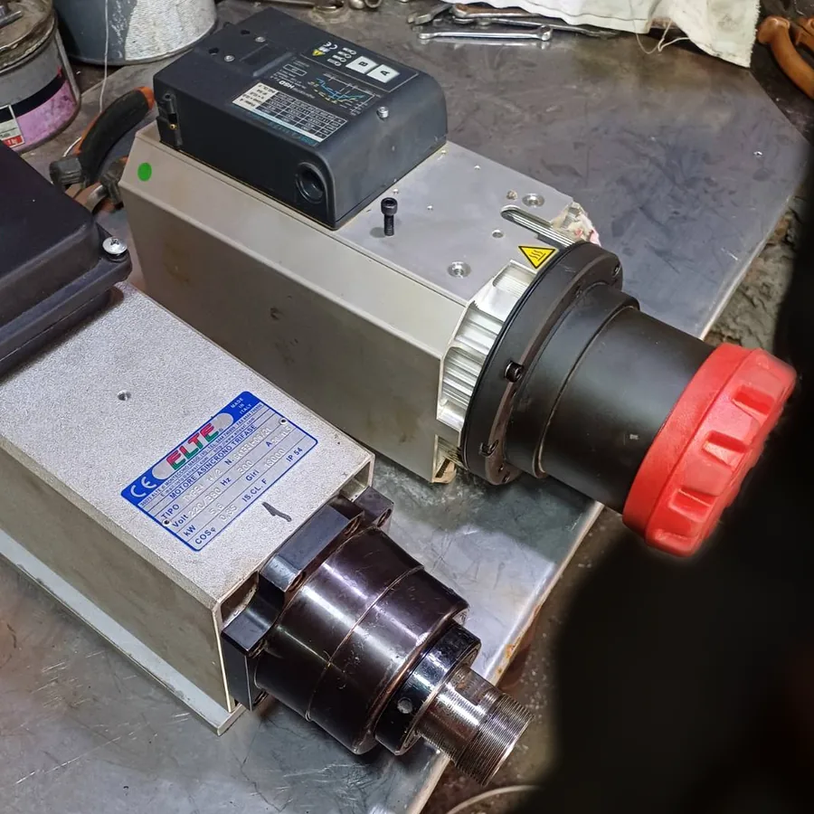
Built-in rotary encoders, magnetic and inductive speed sensors and the pulse rings they read are inspected for wear, cracking and swarf. Air gap and sensor face condition are recorded before anything is disturbed.
Signal checks under measurement
Supply, channel outputs, signal amplitude, phase relationship and the reference pulse are measured on the bench and, where the spindle can be turned safely, while it runs. Intermittent faults usually show up warm rather than cold.
Contamination and cable damage
Oil mist, emulsion and fine swarf on a graduation disc distort the signal long before it fails outright. Cables, connectors and strain relief are checked too, since a broken core inside intact insulation reads as an encoder fault.
Mounting and alignment after a rebuild
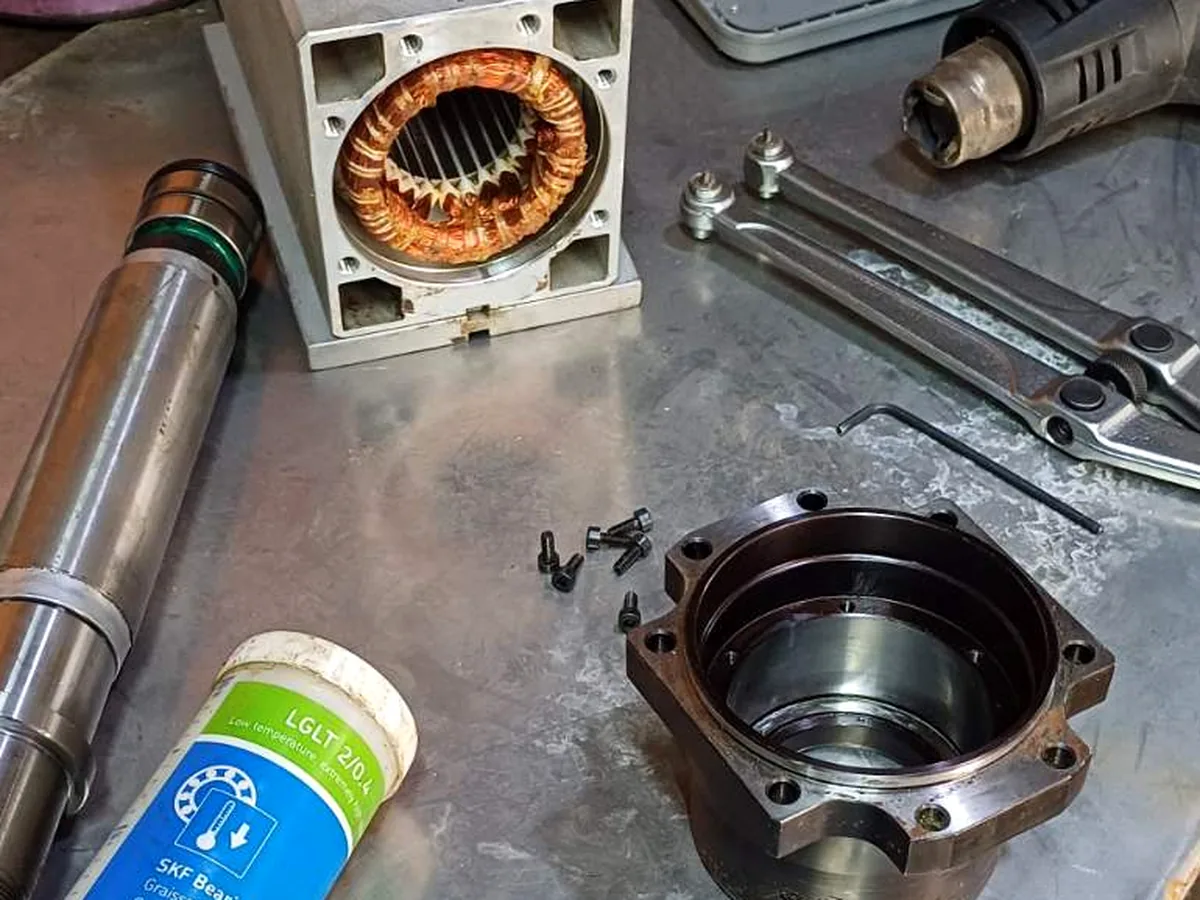
The encoder is refitted with concentricity and axial position set as the design requires, then the orientation reference is checked so that tool change stops where the machine expects it rather than a few degrees away.
Process
Working through the feedback chain
-
1
Start from what the control reported
Alarm numbers, when they appear, and whether they follow temperature or speed all narrow the search considerably before the spindle is opened on the bench.
-
2
Measure the signal
Supply voltage, output channels, reference pulse and cable insulation are measured with the encoder off the machine where possible. The findings are written down with the values.
-
3
Clean, repair or replace
Contamination is removed, damaged cables and connectors are renewed, and where the encoder itself has failed it is replaced with an equivalent type. All of it is quoted first.
-
4
Refit, align and recheck
The encoder is mounted, aligned and its zero reference set. The spindle is then run and the signal recorded again, so the values before and after both appear in the report.
Questions
Encoder and sensor repair spindle repair — frequently asked
No. We work on the spindle: the encoder, its sensors, the mounting and the cabling up to the spindle connector. Drive and control electronics such as Sinamics, OSP or TNC are diagnosed as far as the measurements allow and reported to you, but we neither manufacture nor repair them.
Sometimes. Contamination, a loose mounting, a chafed cable or a corroded connector are repairable and are the cheaper outcome. A worn graduation disc or failed electronics inside a sealed unit are not, and in that case we quote a replacement of an equivalent type instead.
Yes. It is inspected and measured during teardown on every spindle, because refitting a marginal encoder into a freshly rebuilt unit wastes the rebuild. If it needs work, that appears in the written quotation together with the rest of the scope before any repair starts.
Availability of the part usually decides it. A repair is typically five to ten working days from arrival, depending on parts availability and what the teardown reveals. That is an estimate, not a committed date; a binding date is only valid if we confirm it in writing.
Checklist
Useful information for a feedback fault
- Encoder or sensor type, if the label is legible
- Control and drive make, with the exact alarm text
- Whether the fault is cold, warm or random
- Any recent cable or connector work on the machine
Get the feedback fault measured
Send us the alarm text, the control and drive type and the spindle details. We will say what can be measured here and what has to be checked on the machine itself.
Scope
Spindle work we carry out for customers in Encoder and sensor repair
Every operation below is done in our own workshop in Germany. Follow a link for what it involves and what we need from you.
Machine brand
Machine brands
We are independent and not tied to any builder. These are the makes whose spindles come across the bench most often.